User manual
IRIS 3 is software providing a Common Operational Picture (COP), Command and Control (C2), and the collection, processing and distribution of information. This manual covers every screen, setting and function of the app in detail.
00 Overview
What IRIS 3 is, who it is for, and how this manual is organised.
Operational use and scalability
The app is designed to cover every level of command:
- Tactical level (individual soldier): a digital replacement for the paper map and compass, improving situational awareness in the field.
- Command level: command, control and coordination of forces from the smallest tactical element up to brigade level.
Interoperability and communications
Compatibility: the system can be connected to any radio set that supports data transmission.
Field testing: connection and data exchange have been tested successfully with a suitable radio set.
Required equipment: connecting to the radio requires an additional adapter, which can be built locally or in-house from low-cost parts and 3D printing.
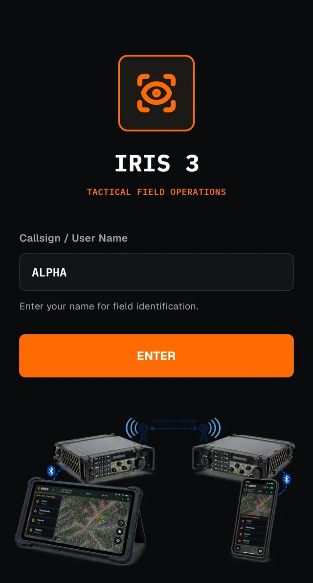
The core of the app is the map (Chapter 02). On it you record targets, observers, text, lines, weapons, points of impact and military symbols (Chapter 03), organised in Layers and also shown in tables (Chapter 04). A separate set of functions covers communications between devices over the wireless bridge: field chat, net check, unit status reports and live position sharing (Chapter 05).
Each section matches one screen or function of the app. The exact labels of buttons and fields as they appear on screen are marked like this: LABEL. Boxes with an amber line are practical tips, boxes with a red line are warnings about actions that cannot be undone, and boxes with a khaki line are cross-references.
01 First Launch
The welcome screen, entering your callsign, and preparing before a mission.
01.1 Welcome screen and callsign
On first launch the welcome screen appears ("IRIS 3 — TACTICAL FIELD OPERATIONS") with a single field: Callsign / User Name. This is the callsign that identifies your device in every entry, message and report it sends. It appears at the top of the navigation drawer, as the source/creator of each target or observer you record, and as the sender of every chat message or net check reply.
Type your callsign and press ENTER. The field cannot be empty; the button does nothing until real text has been typed (the faint "ALPHA-1" inside the field is just an example of the format, not a default value).
The callsign is not locked. You can change it at any time under Settings → PROFILE → User Name (§07). If you later open a saved project file (§06) that contains a different user name, it replaces the current one.
After you enter, the app opens directly on the Map screen, which is the default and permanent start destination. On every later launch the welcome screen is skipped.
01.2 Pre-mission preparation
Before you leave for the field, complete the steps below while a data connection is still available and all the team's devices are together, so shared settings can sync before communication is lost.
- Offline maps — zoom in to the area of operations and press the download button (§02.6) so the map tiles are already stored on the device before the data connection is lost.
- Coordinate datum — confirm under Settings → DISPLAY → Coordinate datum (§02.4) that the whole team uses the same datum (WGS84 or ED50, depending on the paper map that accompanies the mission). A different datum on each device means different coordinates for exactly the same point.
- Set the exact same Network Key on every device under Settings → NETWORK KEY (§07). Without it, no device sends or receives anything over the wireless bridge.
- Register the mission's Fire Units under Settings → FIRE UNITS → Manage Fire Units (§07 / §03.8), so they are ready for target assignment as soon as the mission starts.
- Register the Weapon Types under Settings → WEAPON → Manage Weapon Types (§07 / §03.5), with the correct range for each type.
- Fill in an initial Unit Status (§05.4) with personnel, equipment and ammunition before departure, so the first report sent to the network reflects the unit's real strength at the start of the mission.
If the key is not set, or differs on even one device, Field Chat, Net Check and every other transmission over Channel B fail silently for that device. Check it before every mission, not only at first installation.
02 The Map
The app's main screen, where you will spend most of your time.
02.1 Screen elements
The map is always full-screen (full-bleed); all controls float over it.
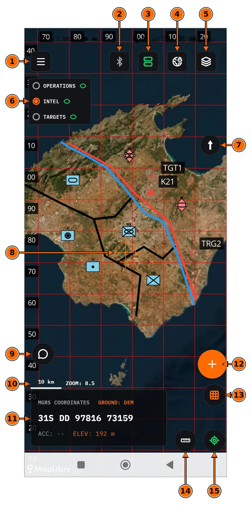
| № | Element | Function |
|---|---|---|
| 1 | ☰ Menu | Opens/closes the navigation drawer, from which you reach every screen of the app. While the drawer is open, the same button becomes a back arrow. |
| 2 | Bluetooth status | Shows at a glance whether the bridge to the radio is connected; tapping it opens the Device Connection screen (§05.1). |
| 3 | Server (Internet) status | Shows the state of the internet connection to other IRIS 3 devices (green when connected); tapping it opens the Device Connection screen (§05.1). |
| 4 | Offline map download | Downloads the currently visible map area for use without a connection (§02.6). |
| 5 | Map background | Opens the Satellite/Vector/Overlay selection panel (§02.5). |
| 6 | Active Layer | Shows which Layer (§04.2) will "receive" the next entry you add (e.g. LAYER: DEMO) and the connection state (OFFLINE when the bridge is not open). When it opens as a list (as in the picture), the orange circle marks the active Layer, and the switch on the right of each row controls whether it is shown or hidden on the map. |
| 7 | North arrow | Shows the map's orientation when you rotate it (§02.2) and resets north to the top. |
| 8 | Crosshair | The fixed reference point at the centre of the screen. It always marks the map point shown in the coordinates panel (11), and is the placement point for several functions (§02.2). |
| 9 | Communication (Chat) | Opens Field Chat (§05.2). |
| 10 | Scale & Zoom | Scale bar (e.g. 10 km) and a numeric zoom level indicator (Settings → DISPLAY → Show Zoom). |
| 11 | Coordinates panel | MGRS coordinates of the crosshair (with a datum label when ED50 is selected), GPS status/accuracy (ACC), elevation (ELEV) and the elevation source (GROUND: DEM) (§02.2). |
| 12 | + Add entry | Opens the menu for adding a new field entity (§03). |
| 13 | Grid | Turns the MGRS grid on the map on or off (§02.3). |
| 14 | Measurement tools | Path measure, distance & bearing, compass or line of sight (§02.7). |
| 15 | GPS centre | Moves the map so the crosshair lands on the device's current GPS position. |
02.2 Gestures & crosshair
The map uses the usual touch gestures: drag to pan, pinch with two fingers to zoom in or out, and rotate with two fingers. On an entry:
- A single tap on an entry opens its details card (§03.0).
- A long press on a Target opens the Fire Unit assignment menu (§03.8).
- A double tap on the last point of a line being drawn finishes it (§03.4).
The crosshair at the centre of the screen never moves by itself. It stays pinned to the centre, and it is the map that moves beneath it. The coordinates panel always reads the position under it. In modes that move an entry, the on-screen instruction is always the same: "Move the map so the central cross shows the new position, then press Confirm".
02.3 MGRS/UTM grid
The red grid of lines over the map follows the UTM/MGRS system. The grid spacing adjusts automatically to the width of the visible area:
| Visible map width | Grid spacing |
|---|---|
| up to 5 km | 1 km |
| 5 – 50 km | 10 km |
| over 50 km | no grid |
To turn the grid on or off: Settings → DISPLAY → MGRS Grid. A second, independent setting, Grid Numbering OFF by default, adds 2-digit labels (the same digit pair that appears in the MGRS coordinates box itself) along the top and left edges of the screen, like the margin of a field map, at both grid spacings (1 km and 10 km).
02.4 Datum: WGS84 / ED50
The datum sets the geodetic reference system in which all MGRS coordinates in the app are displayed and entered:
- WGS84 — the global reference system, and the default. It is what the device's GPS reports.
- ED50 — the system used by many paper maps, for matching against a paper map. A (ED50) label next to the MGRS label on screen reminds you of it.
The datum choice changes only how coordinates are displayed and entered. Data is always stored and transmitted in WGS84. The red MGRS grid follows the selected datum: in ED50 it is recomputed on the International 1924 ellipsoid, so its lines and numbers always match the same coordinate reading shown in the panel, rather than the WGS84 grid shifted by about 100–150 m.
To switch: Settings → DISPLAY → Coordinate datum.
02.5 Map background
The layers button opens the "Map background" panel with three modes:
| Mode | Description |
|---|---|
| Satellite | Satellite imagery (the default; it needs no file import and is covered by the area downloads in §02.6). |
| Vector | A map of roads, settlements and place names in a line-map style, instead of satellite imagery. It requires importing your own .mbtiles file. |
| Overlay | Roads, settlements and place names drawn on top of the satellite imagery, combining both. |
For Vector/Overlay you need a .mbtiles map file with vector layers (vector tiles), e.g. an OpenMapTiles export. The Import map file… button opens the Android file picker. The app rejects files that are not valid .mbtiles or that contain no vector layers. Several files can stay registered at once (e.g. one for each area of operations), but only one is active at a time, selectable from the list. If the active file does not cover the area you are looking at, the reminder "The active map does not cover this area" appears.
Vector/Overlay data comes from the OpenStreetMap project; see §09 for the full attribution.
02.6 Offline maps
The download button in the top bar downloads satellite tiles for the currently visible area of the map so they remain available without a connection. While downloading, a progress bar "Downloading map... N%" is shown. Completion or failure is reported explicitly, and you can cancel while it is in progress.
The list of already downloaded areas is under Maps (offline) in the navigation drawer. There, each stored area can be shown or hidden, or deleted permanently from the device.
02.7 Measurement tools
The ruler button opens a small drop-down menu with four tools. Pressing the same button again while a tool is already active turns it off directly, without reopening the selection menu.
| Tool | How it works |
|---|---|
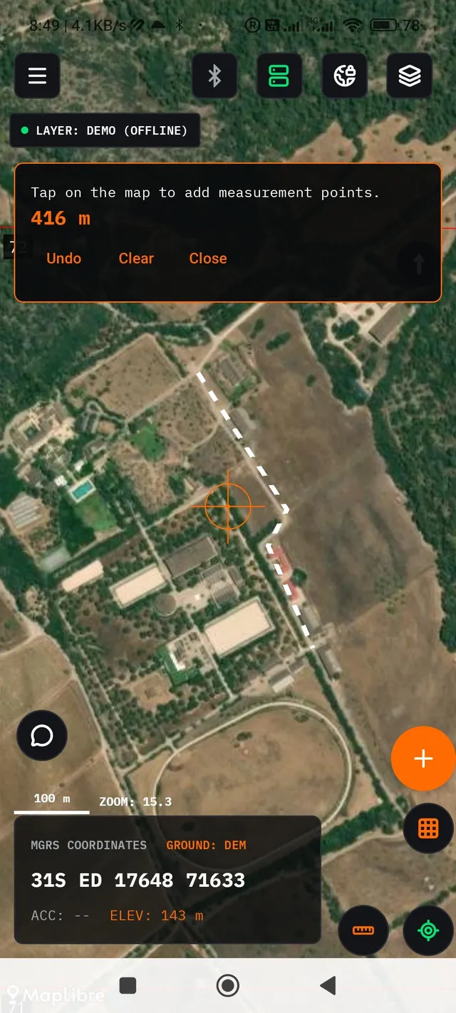
| Path Measure | Each tap on the map adds a point to a multi-segment path, and the total distance updates live (the sum of all segments, not a straight line from the first to the last point). Undo removes the last point, Clear removes them all, and Close leaves the tool. Nothing is saved; it is purely a temporary measurement. |
| Distance & Bearing | One tap sets a reference point. From then on, the distance and bearing (the angle from grid north, not true north) to the crosshair update live as you move the map, with no second tap needed. Clear removes the reference point, and Close leaves the tool. |
| Compass | A live digital compass around the crosshair, with a numeric azimuth and tilt reading in a separate panel. It needs no tap on the map; details below. |
| Line of sight | Line of sight (LOS) between two points, with a visibility calculation based on the terrain relief; details below. |
Path Measure
Each tap on the map adds one more point to the path. The live reading in the panel shows the sum of all segments up to that moment, like the Google Earth ruler, not the straight-line distance from the first to the last point. Undo removes only the last point (disabled while there are none), Clear removes them all, and Close leaves the tool. Unlike a Line (§03.4), there is no double tap to finish. Nothing is saved; it is purely a temporary measurement that is lost as soon as the tool closes.
Distance & Bearing
A single tap sets the reference point. After that no further tap is needed. Since the other end of the measurement is always the crosshair (the centre of the screen), the distance and bearing update live simply by moving the map. The bearing is calculated from grid north, not true or magnetic north, and shows as "—" when there is no valid value for that point. Clear removes the reference point (so it can be set again with the next tap), and Close leaves the tool.
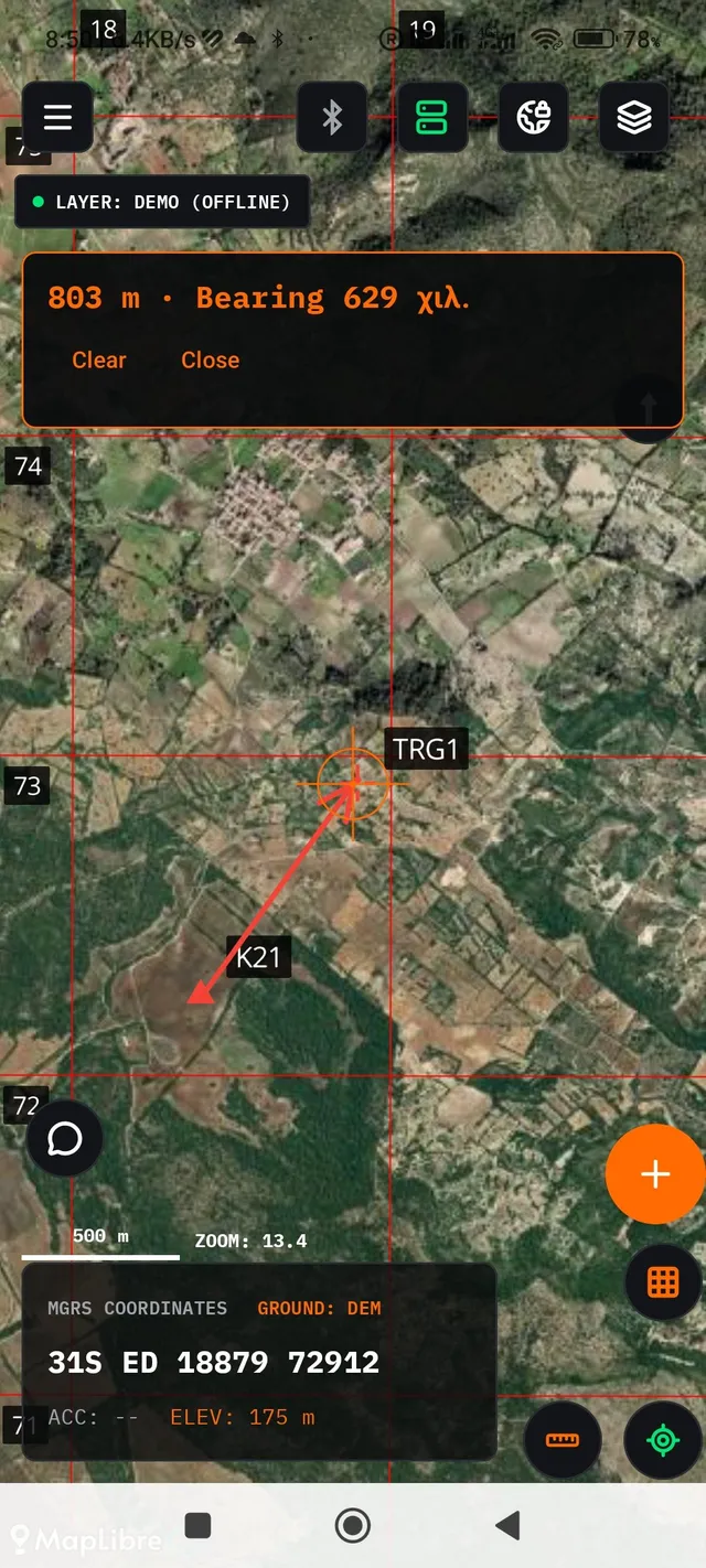
Both measurements are shown in the unit selected under Settings → DISPLAY → METRES/FEET. In METRES the reading switches automatically to kilometres above 1000 m, and in FEET it switches to miles above 5280 ft, so a multi-kilometre measurement does not appear as a long string of digits.
Compass
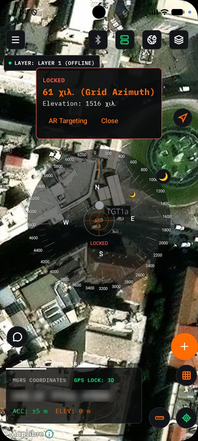
The Compass panel shows the current azimuth (together with the active reference system: True Azimuth/Magnetic Azimuth/Grid Azimuth, chosen under Settings → COMPASS → North Selection) and the device's tilt. Optionally it also shows the current magnetic declination if the Show Magnetic Declination setting is on. Around the crosshair, a graduated ribbon appears in angular mils, in CIRCULAR or LINEAR form and with tick spacing of 100 or 200 mils, all adjustable under Settings → COMPASS. The circular form also carries a bubble level for the device's tilt/roll.
Pressing and holding on the ribbon "freezes" it at the current reading (a LOCKED label in a red outline) for as long as you hold. Lifting your finger returns it immediately to the live reading. If the Show Sun/Show Moon settings are on, the two celestial bodies appear as markers on the ribbon whenever they are above the horizon, and tapping one opens a small panel with its data. While the Enable Camera with Compass setting is on and Camera permission has been granted, the Compass panel also has an AR Targeting button, which opens a camera view with a real-time azimuth/tilt overlay.
Line of sight (LOS)
The first tap on the map sets the Observer and the second sets the Target (a third tap replaces only the Target, keeping the Observer). Undo removes the last point, and Clear removes them all. Once both points exist, the Observer Height (m) and Target Height (m) fields appear (eye/sighting height above the ground, not elevation) and the Calculate button becomes active.
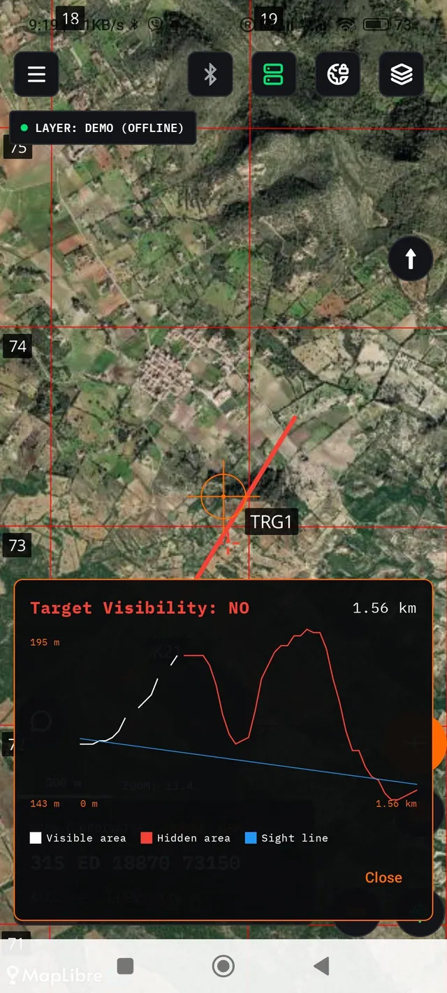
The result is shown as a terrain profile graph: a white line for visible relief, red for non-visible, and blue for the straight Observer→Target line of sight, with a Target Visibility: YES/NO reading and the total distance. The terrain analysis is based on elevation tiles (DEM) stored on the device. If the Observer–Target path passes through an area without elevation data already downloaded, a "Downloading elevation data... N/M" indicator appears before the calculation.
Unlike the rest of the map, elevation tiles are not downloaded together with the offline map download (§02.6). They are fetched on the spot, only when needed, over a data connection. Without a connection and without tiles already downloaded for the area, the LOS calculation fails with the message "Could not download elevation data for the path" or, if elevation is missing exactly at the Observer/Target point, "No ground elevation found for the Observer or Target point". Prepare these two areas while a connection is still available, before leaving for the field.
03 Field Entries
Seven types of object can be placed on the map. All of them share the same basic card pattern.
The + button on the map opens the "NEW ENTRY / ADD ENTITY" menu with seven options:
| Type | Menu label | Use |
|---|---|---|
| Target | Target | A point of interest/targeting; can be assigned to a Fire Unit (§03.8). |
| Observer | Observer | The position of an observer/field sentry. |
| Text | Text | A free text label on the map. |
| Line | Line | A multi-point polyline (route, boundary, etc.). |
| Weapon | Weapon | A weapon system; shows a range ring around it. |
| Point of Impact | Point of Impact | A burst/impact point, with a fire correction field. |
| Symbol | Symbol | A NATO APP-6 military symbol (§03.7); local only, it is not transmitted to the network. |
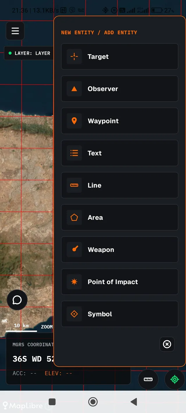
After you pick a type, the next tap on the map (or, for Target/Observer etc., the current crosshair position) opens the creation form for the new object.
03.0 Common card pattern
Every recorded entity shows the same details card structure when you tap it on the map or in a table:
ENTITY TYPE
Four actions are always available on a card:
- Edit — opens the card's fields for direct change (name, description, colour, etc.), with Save/Cancel.
- Move — closes the card and enters move mode: drag the map so the crosshair shows the new position, then Confirm (for Lines, the editing of its points reopens instead).
- Send — opens the Channel A/B/C selector (§05.6) to share this single entry as text.
- Delete — permanent deletion, always behind a confirmation dialog.
Each entry also carries, with no action needed, its own permanent details: the MGRS coordinates in the selected datum, the elevation, the callsign that created it (SOURCE / CREATOR) and the exact time it was recorded.
03.1 Target
Fields: Name, Description, Identification Colour (red/blue/green/yellow/black). It can additionally be assigned to a Fire Unit; see §03.8.
03.2 Observer
The same structure as a Target (Name, Description, Identification Colour), without the fire assignment function.
03.3 Text
Fields: the Text itself, Font Size (Small / Normal / Large / Very Large) and Identification Colour. Use it for free notes on the map that do not match any other type.
03.4 Line
While creating, each tap on the map adds a point to the line. Undo removes the last one, and a double tap on the last point (or the Finish button, active from 2 points up) completes it. A Line's card shows POINTS instead of coordinates/elevation, and the "Move" action reopens the editing of its points rather than shifting the whole line.
03.5 Weapon
Instead of a free colour, a Weapon picks a predefined Weapon Type from a list. Each type carries its own name, description, range (km) and colour, managed centrally under Settings → WEAPON → Manage Weapon Types. Every recorded Weapon on the map automatically draws a range circle around itself, with a radius equal to its type's range and coloured in the type's colour, which is useful for quickly visualising coverage.
03.6 Point of Impact
Fields: Name, Description, and an extra Correction field (fire/point correction) that replaces the colour picker. A Point of Impact's icon is always the same fixed red burst symbol.
03.7 Military Symbol
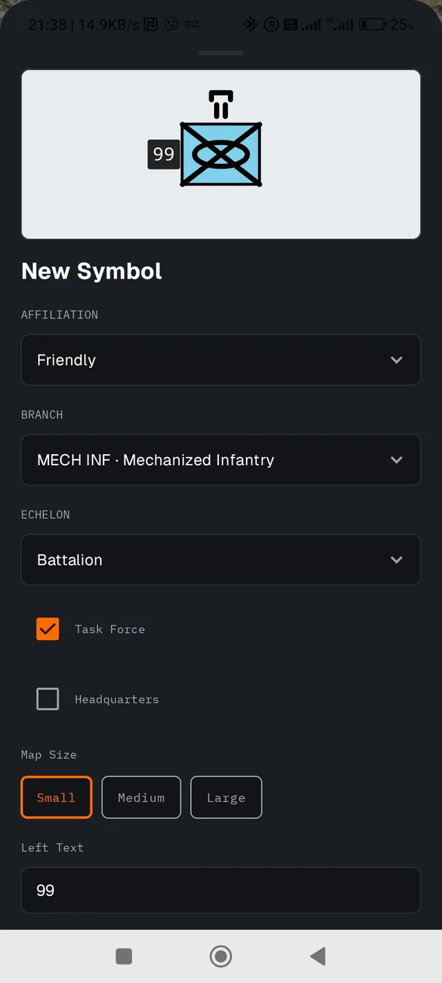
A full NATO APP-6 style symbol, with these fields:
| Field | Options |
|---|---|
| Affiliation | Friendly · Hostile · Neutral · Unknown |
| Branch | Infantry, Mechanized Infantry, Armour, Artillery, Air Defence Artillery, Engineers, Signals, Army Aviation, Supply & Transport, Technical, Ordnance, Medical, Mobile Surgical Unit, Special Forces, or None |
| Echelon | Squad · Platoon · Company · Battalion · Regiment · Brigade · Division, or None |
| Left / Right Text | Free labels beside the symbol (e.g. a unit number) |
03.8 Assigning a Target to a Fire Unit
A long press on a Target opens the menu titled "Target: <name>". If the target is already assigned, the label "Assigned to: <unit>" appears with a Cancel Assignment option. Otherwise there is only Assign to Fire Unit, which opens a list of the available Fire Units. If none has been registered yet, the reminder "No Fire Units: add them from Settings" appears (Settings → FIRE UNITS → Manage Fire Units, where each unit is registered with a name and a weapon system).
A new assignment automatically creates a message in Field Chat (§05.2) and shows a ring around the target on the map. The full picture of all assignments is shown in Fire Distribution (§04.3).
04 Tables & Layers
A list view of the field entries, and how they are organised into layers.
04.1 Entity tables
Three tables in the navigation drawer (Targets Table, Observers Table, Weapons Table) show all the matching entries in a list, with two filters at the top:
- Layer filter — shows only the entries of one specific Layer (or "All").
- Source filter — shows only the entries of one specific callsign (useful when many devices record into the same project over the wireless bridge).
Each row offers three direct actions without opening the card: Go to (centres the map on the entry and shows the map screen), Send (Channel A/B/C, §05.6) and Delete.
04.2 Layers
Layers organise field entries into separate levels that can be switched on and off. This is useful for separating, for example, your own data from another team's data, or one scenario from another. The Layers screen shows their list with the number of objects in each one, and allows:
- Activating a Layer: the next entry you add on the map will belong to it.
- Showing/hiding a Layer on the map, independently of whether it is the active one.
- Renaming and Sending (in bulk, all the Layer's objects).
- Deleting: deletes the Layer and all its entries permanently. The last remaining Layer cannot be deleted.
- + NEW / ADD: adds a new empty Layer.
04.3 Fire Distribution
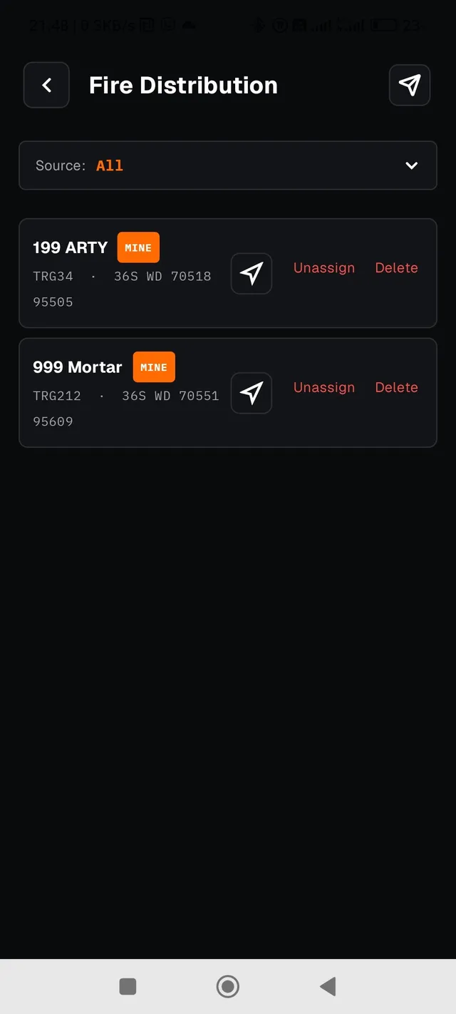
The Fire Distribution screen gathers in one table every Target→Fire Unit assignment (§03.8), both your own (marked MINE) and those received from other devices over the wireless bridge. Each row offers Unassign (undoes only the assignment) and Delete (deletes the target permanently). A send button in the top bar sends the whole table over Channel A/B/C (§05.6).
04.4 ROE
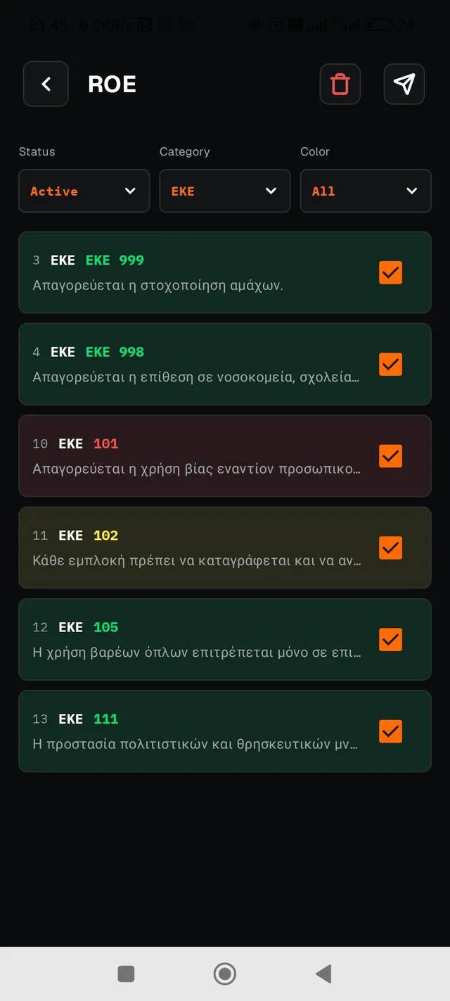
The ROE screen (Rules of Engagement) manages a table of rules imported from a .csv file, with one enable switch per row as the only possible edit. No other row editing is supported.
Importing a file
While the table is empty, only a Select ROE file (CSV) button is shown. The file must be delimited with a semicolon (;), not a comma, encoded in UTF-8, and have six columns in this order (the first row is always a header and is ignored whatever its content): No. · Category · Code · Description · Colour · Enabled.
If even one row has an invalid number of columns, an unrecognised colour, a duplicate number, or an enable value other than TRUE/FALSE, the entire import is rejected, not just the problem row.
Accepted values of the Colour column (they must be written in Greek, exactly as shown):
These are, in order: red, yellow, green, orange, blue and no colour.
Filters & rows
Three filters at the top (Status (Active/Inactive/All), Category and Color) show the filter title above and a drop-down value box below. Each row shows the number, the Category and the Code (coloured according to its Colour), is tapped to expand/collapse the Description, and carries an Active/Inactive checkbox.
Sending & deleting
The Send button sends over Channel A/B/C (§05.6). Channels B/C send, per row, only the number and the enabled state, never the Category/Code/Description/Colour, since every device on the network has already imported the exact same CSV file, so the other columns are identical on all devices in advance. The Delete button empties the whole table. It is the necessary first step before importing a new CSV file, since the file selection button reappears only when the table is empty.
05 Communications
Exchanging data with other devices over the Bluetooth wireless bridge.
All the functions in this chapter require an active connection to another device, either over Bluetooth to an external wireless bridge (typically a radio with an ESP32 in between), or over the Internet directly to another IRIS 3 device that you have paired using a QR code (§05.7–§05.8). Without either, the app remains fully functional for local use (map, field entries); no communication simply reaches another device.
05.1 Device Connection
The Device Connection screen shows the real-time System Status:
| Status | Meaning |
|---|---|
| ONLINE | Connected: communication is working. |
| SYNC | Connecting or reconnecting. |
| OFFLINE | Disconnected. |
Below it, the AVAILABLE DEVICES list shows the Bluetooth devices already paired in Android. Pairing is done first from Android's own Bluetooth settings, not inside IRIS 3. After you select one, the CONNECT / DISCONNECT buttons control the connection. A separate LAST DEVICE panel remembers the last successful connection for quick reconnection. A SCAN button refreshes the list.
The transmission rate (Baud Rate, 9600 to 115200) is set in Settings (§07) but, note, it is only stored and is not yet applied automatically to the active connection.
The connection is organised in two steps: first the Network Key (§07), without which the second step stays locked, and then the connection itself, with two independent collapsible panels, Bluetooth and Server. Each panel opens/closes with its own button. They can be open and connected at the same time: Bluetooth to the wireless bridge, and Server to another IRIS 3 device over the Internet (§05.7–§05.8), not just one or the other. The Server panel carries the KNOWN DEVICES list (the devices you have paired with by QR code) with a CONNECT button on each row.
In the same Server panel, below the Known Devices, the GROUPS section lists the recipient groups you have created or been added to. They are used as a destination on Channel C (§05.6). The New Group button opens a form with a Group Name and a member selection list drawn from your Known Devices (the list shows "No paired devices yet" if it is empty). Only the creator of a group sees the ⋮ → Edit/Delete menu on it; for every other member only the name is shown. Delete always asks for confirmation and is permanent.
05.2 Field Communication (Chat)
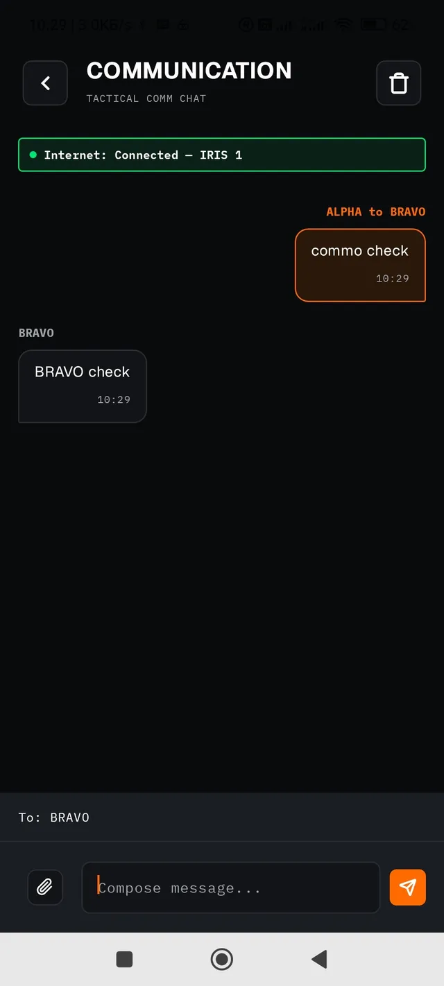
A simple text chat between devices on the same network. Each bubble shows the sender's callsign. Very long messages collapse automatically with a More/Less link. Messages generated by assigning a Target to a Fire Unit (§03.8) show the target as a live link; tapping it closes the chat and goes to the map, centred on it. The Delete Chat button in the top bar permanently deletes the whole history of the current chat.
Two related settings: Message Received Notification and Chat Pop-up (§07, COMMUNICATION).
Sending a file
The paperclip icon next to the compose field opens Android's file picker, for any file type with no format restriction. A file larger than 60 KB is rejected immediately with a clear message, without any attempt to send it.
On the recipient's side, the file is saved automatically to the device's Downloads folder as soon as the transfer completes; no action is needed. The bubble shows the file name and size, and tapping it opens the file with whichever app on the device handles its type. If saving fails, the bubble shows an error indicator instead of being openable.
The wireless bridge transmits each message in chunks of 255 bytes, with an upper limit of 255 chunks in total. This is a hard limit of the protocol, not an adjustable option. If even one chunk is lost in transmission, the whole file is re-sent from the beginning, not just the lost chunk. The size limit is deliberately kept small so that such a repeat does not noticeably load the link.
05.3 Net Check
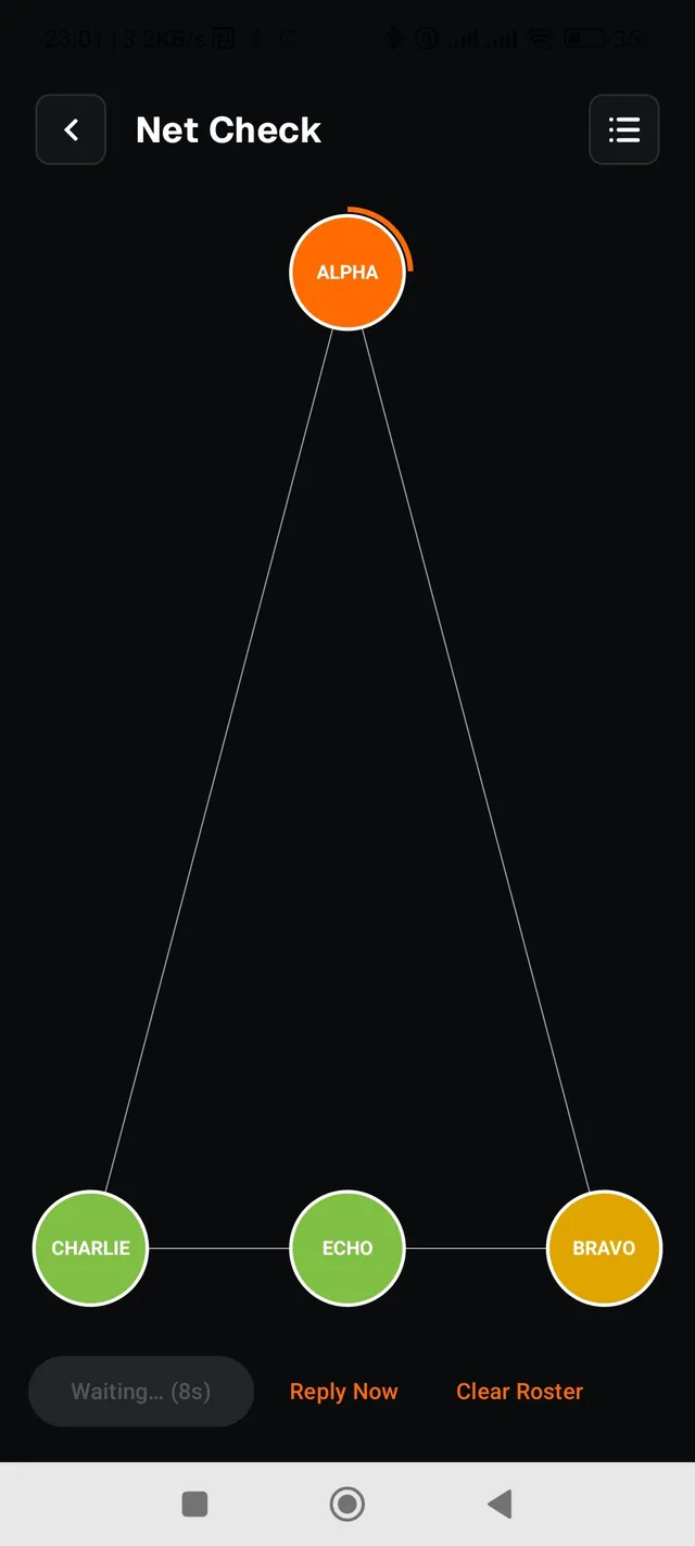
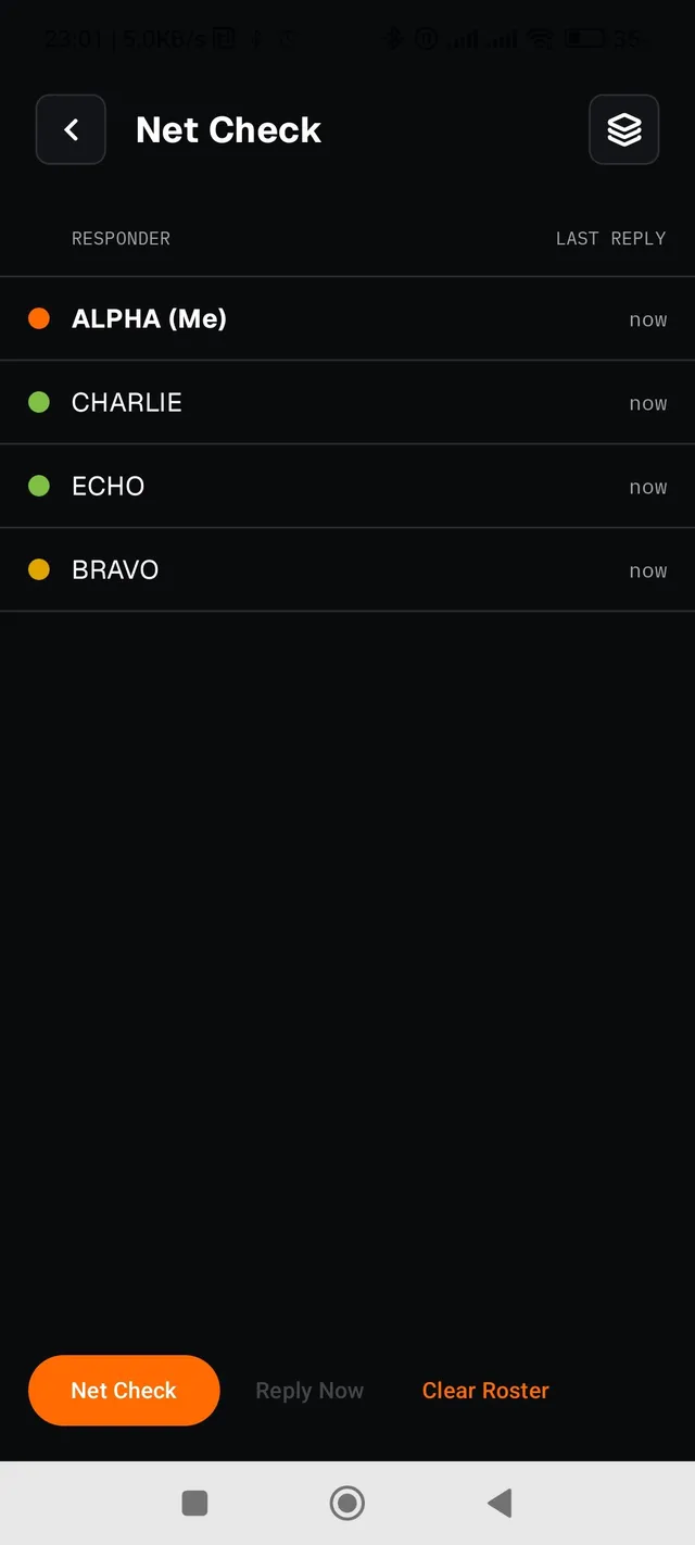
A one-tap "radio check call". When you press Net Check, your device broadcasts a request. Every other device on the network answers automatically with its callsign, after a short random delay so that they do not all answer at once. The result is shown in real time either as a network diagram (your own device at the top, the replies around it in order of arrival) or as a table. You switch with the icon in the top bar, and it always starts on the diagram.
| Node colour | Meaning |
|---|---|
| ● | The device that started the check. |
| ● | Replied on time. |
| ● | Replied, but late (weak link). |
| No fill | Known on the network (replied to an earlier check) but silent in this one. |
A permanent responder roster remembers every callsign that has ever replied, regardless of project. A long press on a node/row removes it, and Clear Roster removes them all. The Reply Now button allows a manual reply to an active check (enabled only while a collection window is open).
Two settings under Settings → NET CHECK: Auto-reply to net check ON by default (turn it off for radio silence: the device will not reply automatically, but still sees the diagram) and Reply window in seconds (the random reply delay ranges from 0.5 s up to this value).
05.4 Unit Status
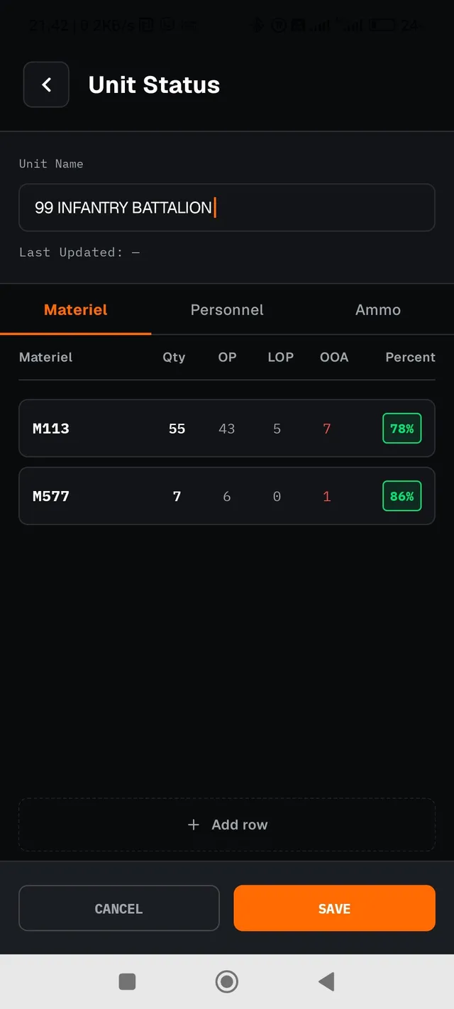
A structured readiness report, in the spirit of a military status report: Unit Name, a personnel table (Officers/Other Ranks, with columns Authorised/Present/Sick-Absent/Casualties/Percent), an equipment table (free-form rows with Qty/OP/Sick-Absent/Percent) and an ammunition table (Type/Initial/Present/Percent, with an Add row option). The screen also shows when the Last Updated took place, and offers Send (Channel A/B/C, §05.6), Edit and Reset (resets all fields, behind a confirmation dialog).
Your own report is always a single one, local to the device. The reports you have received from other devices are gathered in the Unit Statuses screen (plural), with yours always marked MINE.
05.5 Live Position
When you turn on Settings → LIVE POSITION → Share Position (requires Location permission, §08), your device automatically broadcasts its GPS position every number of seconds you set in the Broadcast Interval (sec) field. The same box, with the same switch and interval field, also opens as a short pop-up panel with a long press on the GPS centre button (§02.1, item 15), without leaving the map for Settings. Both places read and write exactly the same value.
The minimum allowed interval changes automatically with the active connection leg: 60 s while Bluetooth (§05.1) is connected, so the wireless bridge is not overloaded, or 3 s while only the Internet is connected, or neither. Bluetooth takes precedence when both legs are connected at the same time. A value below the current minimum is not accepted, and the warning "Minimum Ns" appears.
Positions you receive from other devices appear live as markers on the map, with the matching callsign and a relative age indicator beside it (now / Nm / Nh). The marker blinks to stand out from the other map elements, and its opacity decreases in three steps as the position "ages": full strength up to 2 minutes, reduced up to 10 minutes, strongly faded after that. It never disappears completely, since the last known position remains useful information.
A long press on a responder position marker opens the menu "Hide position <callsign>" with a single action, Hide, which removes the marker (and its trail, if shown) from the map until you explicitly show it again.
Responder trail
A second setting, Settings → LIVE POSITION → Show responder trail OFF by default, draws on the map a light grey trail with all the successive positions each responder has sent, a separate line per callsign, behind its live marker so that it does not compete with it visually. The reminder "Current session only" beside the switch means the position history itself is kept only in memory while the app is running (up to 100 points per responder). It is lost on every restart, and is never saved inside the project file (§06).
User Positions
The User Positions screen in the navigation drawer lists every responder from whom you have ever received a position, with the age of their last position and two independent switches per row: one for the visibility of the marker itself on the map (equivalent to Hide above, but reachable without having to find the marker on the map), and one for the visibility of that responder's own trail. The second always works together with the general "Show responder trail" switch: both must be on for that responder's trail to be shown. A bin button permanently deletes a responder's trail history, without affecting their live marker.
05.6 The "Send" pattern: Channel A / B / C
Every Send action throughout the app (entry card, table row, Layer, Fire Distribution, Unit Status, ROE) first asks where to send:
| Option | How it works |
|---|---|
| Channel A (Share) | Opens Android's standard share menu (SMS, email, messaging apps, etc.) with ready-made text describing the entry. Always available. |
| Channel B (Via bridge) | Sends the data digitally over the Bluetooth wireless bridge to every other connected device on the network: a broadcast, not a chosen recipient. Available while the Bluetooth panel (§05.1) is connected. |
| Channel C (Via server) | Sends over the Internet, through the rendezvous server (§05.7), to one specific recipient that you choose immediately afterwards in a second window: a Known Device or a Group (§05.1). It is never a broadcast to the whole network. Available while the Server panel (§05.1) is selected or connected. |
Choosing Channel C (Via server) immediately opens the Select recipient dialog with the list of your Known Devices and Groups. If the list is empty, it shows "No saved recipients." rather than staying silent. When you pick a Group, the send over the server is addressed to all the members of that group: not to the whole network, as with Channel B, but exactly to the members you defined when creating the group.
The dialog always has an explicit Cancel, separate from the three options, precisely so that sending data over radio or the Internet cannot be triggered by accident.
05.7 Pairing devices over the Internet (QR)
A registered rendezvous server address in Settings (§07, RENDEZVOUS SERVER). Without it, the Rendezvous Pairing screen shows "No rendezvous server address has been set."
The Rendezvous Pairing screen in the navigation drawer has two tabs:
| Tab | Function |
|---|---|
| Generate Code | Automatically creates a unique pairing code and shows it as a QR code and as plain text, with a countdown to its expiry ("Expires in Ns" / "The code has expired"). Show the screen to the device that will scan it. |
| Scan Code | Opens the camera (requires Camera permission) to scan another device's QR code. On success: if the device is new, it asks for a name ("Name this device") before saving it to Known Devices (§05.8). If it is already known, it goes straight to "Pairing successful." |
A code that has expired or is invalid is rejected with the message "Invalid or expired code". You cannot pair with your own device.
05.8 Known Devices
The Known Devices screen in the navigation drawer lists every device you have completed pairing with by QR (§05.7). This is the target list for the Internet function in §05.1. A device that has just scanned your own code appears here as "New device: <identifier>" with a name field and a Save button. It enters the permanent list only after you save a name. The Refresh button at the top re-reads the list. This is necessary because the side that generated the code does not automatically see when another device has scanned it.
06 Project Management
Saving, loading and clearing the current set of field data.
A PROJECT group at the top of the navigation drawer manages the project: a .json file holding a complete snapshot of your field data. The group starts collapsed (tap its header to expand) and always shows the name of the current project file beside it, or New Project while you have not yet opened or saved one. Every time the navigation drawer closes, the group collapses again automatically.
- Open Project — opens Android's file picker so you can load a saved project file, completely replacing the current data.
- Save Project — saves the current snapshot. If the project has already been opened/saved from a file, it writes there directly; otherwise it opens the file picker so you can choose where.
- Save As Project — always saves to a new location/name through the file picker, even when the project is already linked to a file; subsequent "Save Project" actions will then write to the new file.
- Close Project — clears the current project and starts a new, empty one, behind a confirmation dialog.
A second collapsed group, TABLES, gathers in the same way the entity tables of §04 (Targets, Observers, Weapons), Layers and Unit Status.
| Included | Not included |
|---|---|
| Layers · Targets · Observers · Texts · Lines · Weapons · Points of Impact · Military Symbols · ROE (§04.4) · your own Unit Status · your callsign | Weapon Types and Fire Units (configured centrally, §07) · the Net Check responder roster · the remembered Bluetooth device · the general Settings |
It permanently deletes all Targets, Observers, Texts, Lines, Weapons, Points of Impact, Military Symbols and the ROE table of the current project, resets the Layers to a single empty one ("Layer 1"), empties your own Unit Status, deletes the Unit Status and Fire Distribution reports you have received from others, and deletes the entire Field Chat history. If you have not first saved with "Save Project", the data is lost for good. It does not affect Weapon Types, Fire Units, the Net Check responder roster, or Settings — these are data of the device itself, not of the project.
07 Settings
A complete reference of every section and option on the Settings screen.
PROFILE
| Option | Description |
|---|---|
| User Name | Your callsign (§01). It can be changed at any time. |
DISPLAY
| Option | Default | Description |
|---|---|---|
| Night Mode | OFF | Dark display theme. |
| METERS / FEET | METERS | Unit used to display distances/altitude throughout the app. |
| Coordinate datum | WGS84 | See §02.4. |
| MGRS grid | ON | See §02.3. |
| Grid numbering | OFF | See §02.3. |
| Show Zoom | ON | A numeric zoom-level indicator next to the map scale. |
COMMUNICATION
| Option | Default | Description |
|---|---|---|
| Baud Rate | 9600 | 9600 / 19200 / 38400 / 57600 / 115200. Only stored — not yet applied automatically to the connection. |
| ACK Timeout | 2 s | How long the app waits for a delivery acknowledgement before trying again. |
| Max Retries | 3 | How many times it retries before giving up on a transmission. |
| Message Received Notification | ON | A system notification when a new chat message arrives. |
| Chat Pop-up | ON | Shows the chat as a pop-up window on receipt. |
| Manage Bluetooth Connection | — | Goes to the screen in §05.1. |
NETWORK KEY
A Network Key field (masked while typing, like a password) and a Save Key button. The exact same key must be set on all the devices of the network. It encrypts communication over the wireless bridge, so devices with different keys cannot exchange data with one another. An indicator below shows whether an active key is already present on the device or, if not, warns explicitly that no communication is sent or received until one is set.
RENDEZVOUS SERVER
| Option | Default | Description |
|---|---|---|
| Server Address | (empty) | The address of the rendezvous server (format https://host:port, without a trailing /) used for Pairing over the Internet (§05.7) and the Internet option in §05.1. Without it, no QR pairing is possible. |
NET CHECK
| Option | Default | Description |
|---|---|---|
| Auto-reply to net check | ON | See §05.3. |
| Reply window (sec) | 7 | Upper bound of the random reply delay. |
LIVE POSITION
| Option | Default | Description |
|---|---|---|
| Share Position | OFF | See §05.5. Requires Location permission. |
| Broadcast Interval (sec) | 60 | How often your position is broadcast; minimum 60 or 3 s depending on the connection (§05.5). |
| Show responder trail | OFF | A trail of positions per responder; current session only (§05.5). |
WEAPON
The Manage Weapon Types row leads to the list of predefined weapon types (§03.5): each type has a Name, Description, Range (km) and Colour, with Save/Delete for each type.
FIRE UNITS
The Manage Fire Units row leads to the list of Fire Units (§03.8): a name and a weapon system for each unit, with add/edit/delete.
PERMISSIONS
Two permission status rows (Bluetooth, Location) — see §08.
EMERGENCY
A complete, irreversible deletion of all data on the device, reached from Settings → EMERGENCY → EMERGENCY CLEAR. The screen lists in detail what is about to be deleted before it is carried out:
| Category | Contents |
|---|---|
| MISSION DATA | Targets, Observers, Lines, Texts; Weapons, Points of Impact, Military Symbols, Waypoints; ROE, Chat history, Unit Status (yours + received), Fire Distribution; the Layers return to a single empty "Layer 1". |
| CURRENT PROJECT | The active project file is deleted from the device, if it is still accessible. |
| DEVICE LISTS | Weapon Types, Fire Units. |
| SETTINGS & PROFILE | User name, night mode, measurement units, datum, MGRS grid, compass, notifications — all return to their defaults. |
| NETWORK & BLUETOOTH | The encryption network key; the remembered Bluetooth device and the ACK/Baud/Live Position settings; Net Check history (roster + results). |
| OFFLINE MAPS | All imported vector basemap files (.mbtiles). |
The action requires holding the "HOLD FOR EMERGENCY CLEAR" button continuously for 3 seconds, not a simple tap, precisely so that it cannot be triggered by accident. Once the clearing completes it is permanent and cannot be undone.
08 System Permissions
The two Android permissions the app requests, and why.
| Permission | Needed for |
|---|---|
| Bluetooth | Connecting to the wireless bridge (§05.1). Without it, there is no communication with other devices. |
| Location | The GPS lock in the coordinates panel (§02.1), centring on your position, and Share Position (§05.5). |
The status of each permission is shown under Settings → PERMISSIONS; tapping a permission that has not been granted requests it. If Android has already rejected the request once and no longer shows its own rationale dialog, the app takes you directly to Android's app settings for manual granting.
09 Appendix
About the app, font/data credits, and a quick colour reference.
About / Help
The About/Help screen in the navigation drawer shows the current version of the app and the data/font credits:
| IBM Plex Mono | IBM, SIL Open Font License 1.1 |
| Geist | Vercel, SIL Open Font License 1.1 |
| Open Sans | Google, Apache License 2.0 |
| OSM Bright | OpenMapTiles, BSD-3-Clause |
| Noto Sans | Google, SIL Open Font License 1.1 |
| Map data | © OpenStreetMap contributors |
Quick reference: identification colours
Targets, Observers, Texts and Lines share the same five-colour palette:
Weapon Types have their own, wider palette of ten colours (Red, Blue, Light Blue, Dark Blue, Green, Dark Green, Yellow, Grey, Black, Orange), defined per type and not per individual entry.
The ROE table (§04.4) has its own separate palette of six colours, set by the Colour column of the imported CSV file (written in Greek, as in §04.4: red, yellow, green, orange, blue, no colour):